I am rebuilding my Arduino-based data collection system. Named the RIMU for some long-forgotten and pointless acronym. My old one used a momentary switch—a button—to change which sensor is displayed on the LCD. It is awful because if the Arduino is busy when you push the switch then nothing happens. I’m fixing it with a 5-position switch sold for changing the pickup combinations on electric guitars.
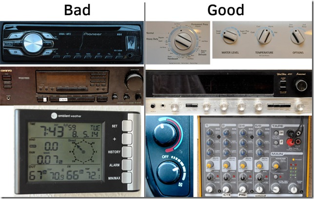
I was thinking about some really good machine interfaces, and some really bad. I walked about the house with a camera. Below are some photo collections of good and bad interfaces around the house.
Good interfaces control devices unambiguously with touch. You should not have to look at the device to know what mode you have changed it to. Really great interfaces, like a light switch, reveal their state by touch.
My switch is almost as good as a light switch. With five states it is hard to tell which state it is in by feeling its position; however, it is easy to change state. Even better, its position is an absolute indication of its state. There is no issue of the Arduino being busy when the state changes, because the state is fixed by the switch. It is not toggled by some transient state.
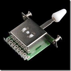
I bought my switch from Sparkfun, and also lifted this product image from them.
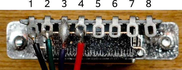
If you can find old rotary switches with detents you can use the analog read function of the Arduino to get all the states with a single pin. In this case, though, I will use three pins to represent the states. I believe it is possible to configure this switch with a few resistors to represent all its states with a single analog input, but it is more complex to figure out and I am not short on pins. My definition of pins. The ones with wires are the only ones I need to use.
With just three digital inputs, the Arduino can read all five switch states. The Arduino’s microprocessor includes built-in pull-up resistors. These are easy to use, but a little bit confusing. A pull-up resistor means that if the pin is not attached to anything, the Arduino will read the pin high.

In the following table I show a Y to indicate how the switch is connected internally. However the ABC column shows what you would read from the pins in the Arduino.
| Pos | 1 | 2 | 3 | ABC | |
| 1 | — | — | Y | 110 | 6 |
| 2 | — | Y | Y | 100 | 4 |
| 3 | — | Y | — | 101 | 5 |
| 4 | Y | Y | — | 001 | 1 |
| 5 | Y | — | — | 011 | 3 |
// Define the spins to read the switch
#define pinSwitch1 2
#define pinSwitch2 3
#define pinSwitch3 4

unsigned char switchState( void){
  unsigned char state=0, in;

  in = digitalRead( pinSwitch1);
  state |= in << 2;
  in = digitalRead( pinSwitch2);
  state |= in << 1;
  in = digitalRead( pinSwitch3);
  state |= in;

  switch( state){
    case 6:
    return 1;
    case 4:
    return 2;
    case 5:
    return 3;
    case 1:
    return 4;
    case 3:
    return 5;
  };
  return 0;
}

void setup( void){
  pinMode( pinSwitch1, INPUT);
  pinMode( pinSwitch2, INPUT);
  pinMode( pinSwitch3, INPUT);
  digitalWrite( pinSwitch1, HIGH);
  digitalWrite( pinSwitch2, HIGH);
  digitalWrite( pinSwitch3, HIGH);
  Serial.begin( 57600);
  Serial.println( 'Started');
}

void loop( void){
  Serial.print( "Switch: ");
  Serial.println( switchState());
  Serial.print( " ");
  Serial.print( digitalRead(pinSwitch3));
  Serial.print( " ");
  Serial.print( digitalRead( pinSwitch2));
  Serial.print( " ");
  Serial.print( digitalRead( pinSwitch1));
  Serial.print( " ");
  delay( 1000);
}


