

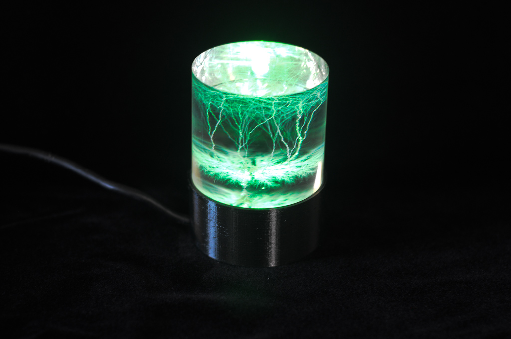
I have a cylindrical acrylic Lichtenberg figure I have been displaying for several years on a turned cherry base I made…and never liked. I decided to improve the situation by building a system for more uniform illumination of the entire column. You can find the major files for this design at Thingiverse:5508486.
My design uses a 3D-printed base which consists of a parabolic dish and a pedestal in the center of the dish that holds a 5 mm LED at the right height. The lead holes in the base accept the LED’s electrical leads which route to the bottom and into a cavity which can be used to connect to a cut-off repurposed USB cable.
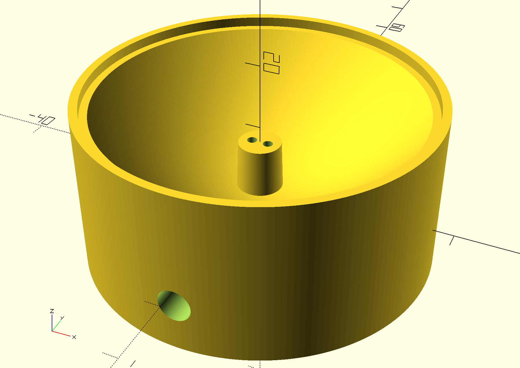
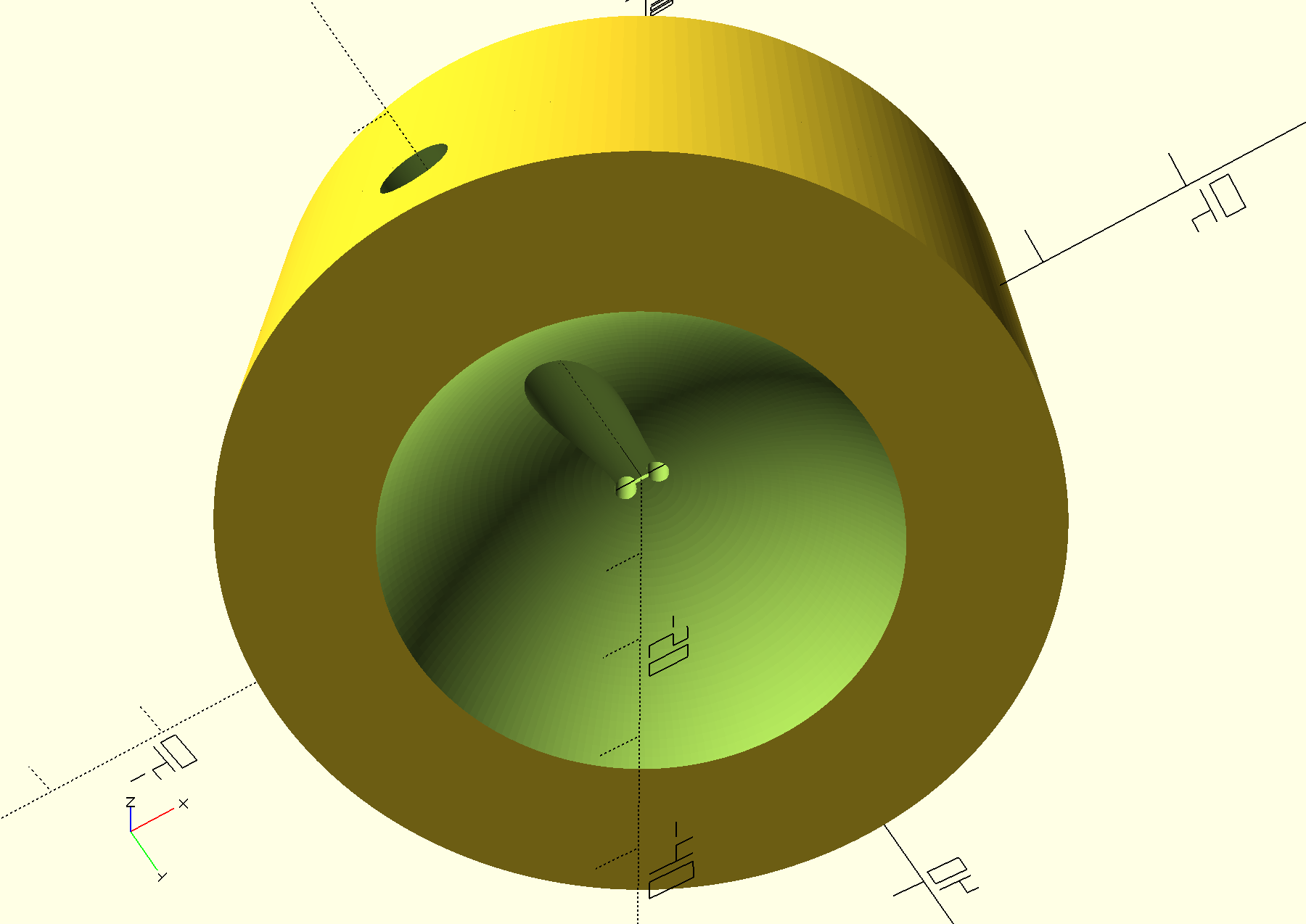
The point of a parabolic reflector dish is that the rays will be departing parallel into the flat base of the acrylic figure. Snell’s law tells us that parallel rays into the flat base will not be refracted, and so to the degree that we have uniform illumination at the base we will have uniform illumination of the inside of the figure. Getting the illumination uniform means suppressing the “hot spot” of direct light from the LED–more on that later.
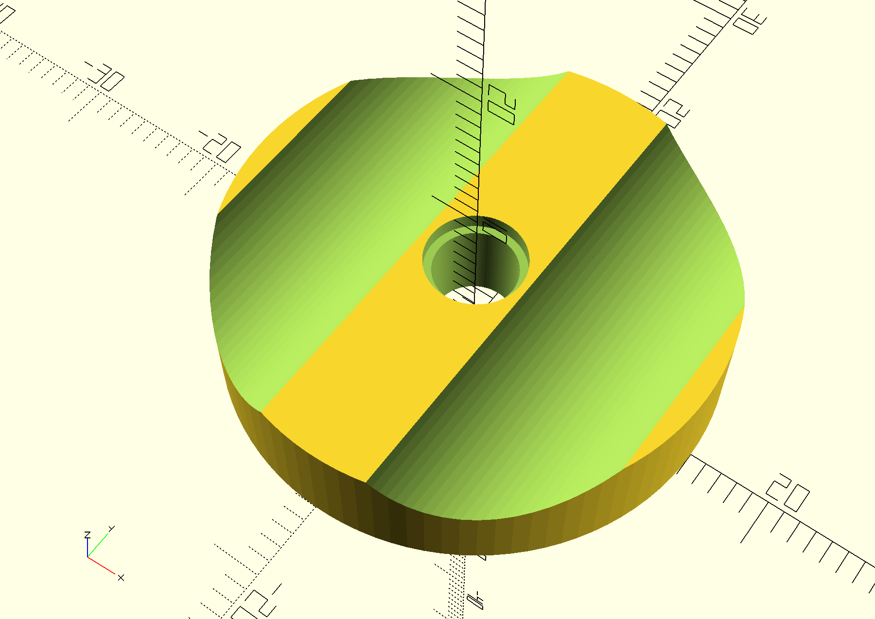
The most compact parabolic base (vertically–all have the same diameter) comes from positioning the LED at the highest feasible point. The vertical height of the LED’s plastic lens becomes a problem in positioning it high within the parabola. Also, I don’t want the hot-spot illumination. To solve that I used wet/dry sandpaper with water to grind the lens off the LED. It was expedient to make a tool for this which would hold the LED at the right length and the right angle. After grinding the LED has a flat top suitable for adhering aluminum foil to. The aluminum foil blocks the “hot spot” and the grinding allows the LED to be positioned high in the paraboloid.
Of course I want to line the paraboloid with a specular reflector, and aluminum foil has both the reflectivity, low cost point, and availability I want. However, aluminum foil is not sold in small parabolic shapes for my application. I needed a way to cut out the foil into a daisy-like petaled structure where the petals could be bent up to complete the lining. I followed a really hard to read paper by Srinivasan, Kulkarni, and Pasupathy which did the math but took me a while to decipher. The basic premise is that there are two coordinate systems, the Cartesian where the paraboloid lives and a different frame along the foil. Every x of the Cartesian plane corresponds to exactly one along-the-curve distance R from the center. Furthermore, every x point represents a circumference “around the bowl” while every value of R represents a certain amount of aluminum foil. We have to cut out a piece of the foil at every distance R so that only the amount of foil needed to cover a circle of radius x remains. Such cutting is difficult, so I made a 3D printed template.
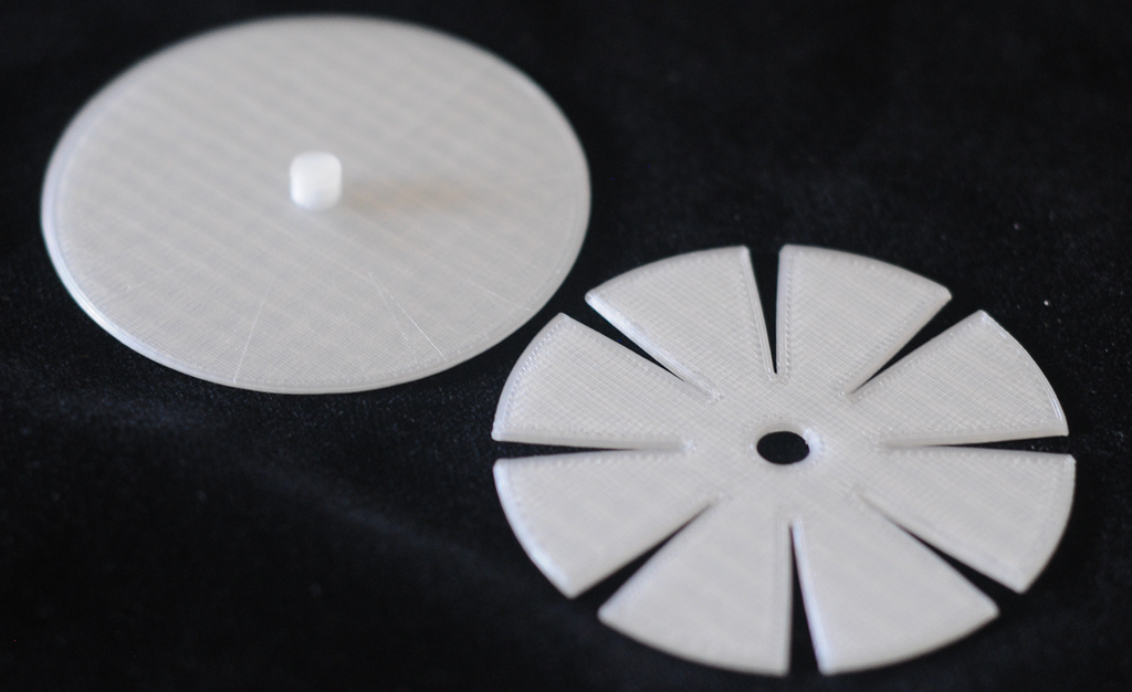
After using the template I cut down the foil and pressed it into the parabolic dish. I did not worry about the structure or stair-stepping left by the 3D printer–the foil seemed to cover adequately. I did not belabor smoothing out the foil since a little randomness is not a problem.
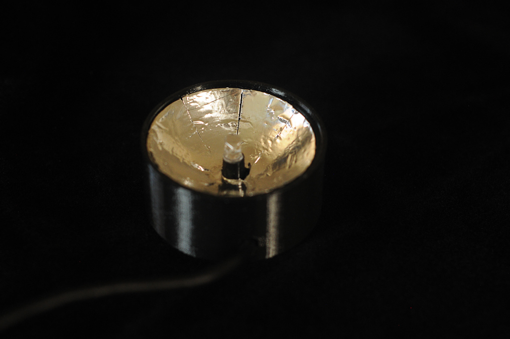
The final product included the wiring and a 100 Ohm resistor potted in cheap hobby epoxy in the back. I epoxied a small circle of foil on top of the LED.
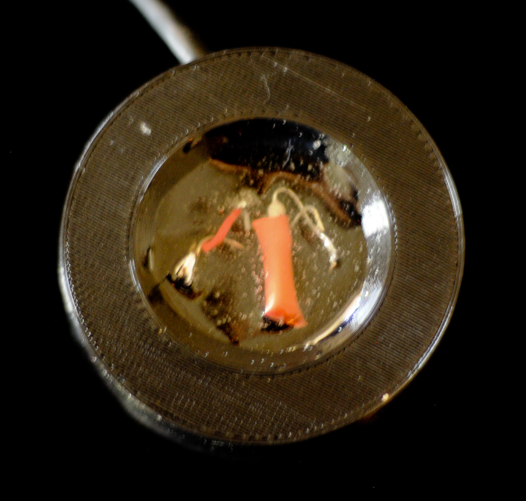
The final result achieves the objectives reasonably well–uniform and efficient lighting across the entire diameter of the Lichtenberg figure. The math was a joy to work through ad though not particularly complex required me to think in unfamiliar ways.
