
I like to use closed headphones. These often significantly attenuate outside noise but challenge me to hear my own voice. Typical attenuation of some relevant headphones or headsets are summarized by the following table.
| Headphone | Attenuation |
| Westone in-ear Monitors | 23 dB |
| Audio Technica ATH-M50 | 11 dB |
| Hyper-X Cloud II | 16 dB |
I want to use these headphones along with an external mic or headset with my mobile phone or, in the age of COVID, with my computer when telecommuting. My children, in online education, are faced with the same need but have less flexibility about what equipment to use since they have district-issued Chromebook devices.
I want direct monitoring, where I can hear my voice combined with the signal from the computer. If you have used a plain old land line phone, then you have experienced direct monitoring of your own voice.
This article is about a circuit that solves the problem by allowing the user to plug his or her headset into the circuit then plug that circuit into the computer or mobile phone. A number of solutions other than this circuit exist but have substantial shortcomings:
- Open headphones, like the Koss Porta Pro allow you to hear your own voice but also hear all the other telecommuting members of your family
- USB sound devices with built-in monitoring and appropriate microphone inputs are rare. I use ATH-M50 headphones and an external dynamic microphone with Focusrite Scarlett Solo and it is excellent. Using it with a headset like the HyperX Cloud II requires stepping down the mic’s phantom voltage with a device like the Rode VXLR+. For a computer this functions excellently, but has drawbacks. It does not work with a phone, it is bulky on the kids’ work surfaces (kitchen table), and costs a lot.
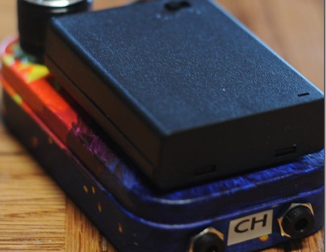
My solution is the a custom circuit packed into a hand-painted Altoids tin, shown in the following picture.

I designed this project to the objectives:
- Plug in a headset and a computer or phone (3.5 mm TRRS Android/Chromebook wiring, as opposed to Apple)
- Wearer can hear himself or herself speaking in the headphones, with no delay or latency
- Wearer can hear the sound from the computer or phone
- The computer or phone receives the signal from the microphone normally
The following figure shows architecture of the adopted basic design. A preamplification stage provides a low noise transimpedance amplifier for the microphone signal. This signal is supplied to the computer or phone. The signal is also passed through a user-controlled variable gain stage that lets the user adjust the volume of his or her voice without changing the signal strength provided to the computer or phone. The final two amplifiers are adders (audio mixer circuits). These combine the mono microphone signal independently with the left and right stereo outputs from the computer or phone.

Finally, I want the circuit to be powered either by a reasonable battery stack consisting of a modest number of inexpensive batteries like AAA or AA or by the USB 5 V supply. USB supplies are often quite noisy and would require at least USB-OTG to work with a phone, so I assumed and implemented battery power for this design.
This report discusses the design of each stage of the circuit in basic architecture figure. The section Signal Analysis analyzes the circuit mainly through simulation results. Finally, the Discussion section covers future directions to take with this circuit.
Preamplifier Design
The preamplifier stage is the most sensitive element of the design. It must be low noise, and correctly bias the microphone. It does not need much gain since the computer or phone are designed to work with the same voltages the electret microphone produces. I followed the design process laid out in the article Single-Supply, Electret Microphone Pre-Amplifier Reference Design by John Caldwell, of Texas Instruments. Designing to a cut-off frequency of around 20 kHz resulted in the design shown by the following figure.

Capacitor $C_2$ is a film capacitor because the voltages are high enough that high-K ceramic capacitors will induce distortion in the signal because their capacitance changes depending on their voltage. Capacitor $C_3$ and $C_5$ AC-couple the circuit to the microphone capsule and to the computer or phone. $R_6$ prevents charge accumulation on $C_5$ which helps prevent a rapid large discharge into the computer.
Between the coupling capacitors is an op-amp transimpedance inverting amplifier. The op-amp used for this is a low-noise, low voltage, rail-to-rail design. I had some OPA4228 chips already, and although there may be better parts like OPA172 or OPAx227 with its unity gain stability, this worked extremely well in a breadboard experiment.
The current from the microphone $i = 16.17$ μA, and we are seeking an output voltage of $V = 100$ mV. These together set the feedback resistor $R_2 = V/i = 6.8$ kΩ.
We need to bias the microphone with $R_1$. The bias voltage on the mic should be $V_{\text{mic}} = 2$ V and we expect a small current through the microphone of about $i = 0.5$ mA. With a $V_{cc} = 5$ V supply,
$$
R_1 = \frac{v_{\text{cc}} – v_{\text{mic}}}{i_{\text{s}}} \approx 5.6\mbox{ kΩ}.
$$
It would also be reasonable to set $R_1 = 6.2$ kΩ, but breadboard experimentation later showed a slight perceived audio preference for the smaller value.
The feedback capacitor $C_2$ creates a single pole filter with $R_2$. Allowing for 0.1 dB ripple in the passband derives a constant 0.989 for calculating the pole frequency $f_p$ from the cutoff frequency $f$ as
$$
f_p = \frac{f}{\sqrt{0.989^{-2} – 1}} \approx 134\mbox{ kHz.}
$$
The cutoff frequency for voice audio is almost certainly less than 20 kHz, but it is reasonable to design to that. Then
$$
C_2 = \frac{1}{2πR_2f_p} \approx 192\mbox{ pF}
$$
assuming $R_2=6.2$ kΩ.
The low-frequency response of the circuit ticks up, a behavior that is inaudible here and can be adjusted by changing the coupling capacitor C3 provided instrumentation is available. In practice it was not terribly important.
Mic Gain Stage
The gain stage schematic in the following figure shows a simple inverting amplifier with gain between 0 and $100\mbox{ kΩ}/20\mbox{ kΩ}=5$. In hindsight we could have used a smaller variable resistor along with a smaller input resistor. The input resistor was chosen after some experimentation, a 10 kΩ resistor was too small, leading to touchy control.

Mixer (Adder) Stage
The final stage is an audio mixer, it is two identical channels each with a separate input resistor for the mic signal and for the computer signal. The gain is fixed, as is the relationship between the mic and computer source gains.

In the generic mixer circuit, the output due to the input $V_1$ is
$$
V_{\text{out}} = -\frac{R_f}{R_1}V_1,
$$
it is negated as expected of an inverting amplifier. All the inputs are combined and negated, so that
$$
V_{\text{out}} =
-\left(
\frac{R_f}{R_1}V_1 +
\frac{R_f}{R_2}V_2 +
\frac{R_f}{R_3}V_3
\right)
$$
is the output–the sum of the inputs negated. In the circuit design we actually have an attenuation in the mixer channel, with $R_f/R_{\text{in}} = 5.6\mbox{ kΩ}/10\mbox{ kΩ} = 0.56$. There is some liberty in setting the gain of this stage, a dual-pull potentiometer is large and to be avoided. In later breadboard experimentation we changed this to a unity-gain circuit and appreciated the consistent computer output that gave us.

Signal Analysis
Oscilloscope inspection of the microphone preamp stage showed gain is proportional to frequency, as expected. Additionally, oscilloscope inspection revealed the expected voltage gains (inverting) including the poorly chosen fractional gain of the mixer stage.


Most of the important frequency modeling is about ensuring reasonably flat response of amplifiers over the passband. The following power spectral density plots show that this is reasonably well achieved. Breadboard experiments have selected slightly more optimal values for capacitors in terms of how things actually sound, but the curves remain fairly similar. Slightly more suppression at low frequencies, and slightly less at high frequencies.


Discussion
The design presented here should certainly be modified:
- The gain of the mixer stage should be unity. This would make the response of the circuit to the computer’s or phone’s volume control work nicely. Unity gain helped in breadboard trials since the boxed version was assembled.
- Assessment of the output with an oscilloscope showed a strange instability. When the variable gain is set approximately mid-range the circuit shows an abundance of high frequency whitish noise. Breadboard trials with the TI OPA172 showed better stability, but of course this is not an all-else-equal comparison.
- The input impedance, $R_{13}$ in the mixer, is set to a fairly large value of 10 kΩ. This means the computer or phone is seeing a load that looks more like a “line in” than a set of headphones. In my experience this can cause noise in the input source to have a very apparent audio character. In other words, the system sounds crummy because the noise from the source is apparent. I suspect either of the alternate designs (depicted below) would help, but I have not tried them. The symptom is often evident with very sensitive headphones (Etymotic ER-4S) and can be treated with an in-line attenuator. I am not clear on whether the power delivered by the phone is lost (sunk to the virtual ground at the negative input of the op amp) or delivered to the load. If it is delivered to the headphones, than the low impedance 32 Ω version could additionally benefit power management. Indeed a non-inverting gain stage might make sense either in the variable gain preceding stage or in a post-mixer design. Presenting low impedance to the computer or phone may not help–some computers or phones work very well when presented with high impedance.
- The gain of each stage in the imagined upgrade is better balanced. The initial pre-amp stage transimpedance amplifier is fixed and is only a little greater than unity so that its output is compatible with receiving phone or computer. The gain stage for the mic is variable, between 0 and about 5× voltage. The mixer stage has unity gain for the computer or phone source, but could easily be configured to have a factor of two or more gain for the mic with only unity gain on the supply from the computer or phone. At the needed gain values relatively little benefit may come from balancing the gains, but it seems like it would be a small improvement.
- The design should be moved to a printed circuit board with surface mount components. The size would be reduced from about 2×3 inches to 1.5×2 inches (50% reduction in area) or smaller, see PCB layout figure at the end of this post.
- This design has not been, in any way, optimized for total system power. I cannot even compare the ratio of quiescent power to dynamic power–and this seems somehow to suggest possible improvements.


